< | Help Index | >

|
Creating and Editing Keypad Files
|
Creating A New Keypad File
To create a new Keypad File, select "New" from the "File" menu. A blank Keypad File
will appear and the Edit Info window for the file will open. You should confirm the test
configuration and default values before proceeding.
Note: You can change this
information later by selecting "Edit Info..." from the "Edit" menu or clicking on the Edit
Info tool button. See Edit Info window below for more
information.
Opening An Existing Keypad File
To open an existing Keypad File, select "Open" from the "File" menu or double click on the
file in the file browser on the left side of the screen.
In order to edit a Keypad File you must be in the Edit Keypad File mode. To enter the edit mode select
"Edit Keypad File" from the "File" menu.
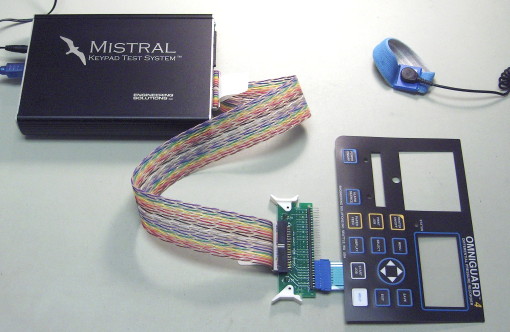
Learning A Keypad File Automatically
The Mistral was designed to make defining a new Keypad File fast and easy. First create a new
file as described above. Connect a known good
Keypad to the pod using the cable and test adapter provided. You can plug the keypad into any pins
on the adapter (except pins 31 and 32 on a 30 point system) but you must be sure to connect it the same
way when you are testing.
Click on the Learn Keypad File tool button (it looks like a magic wand) to begin learning the keypad. After
confirming that you have a Keypad attached the system will automatically begin learning, looking
first for permanent connections and LEDs. The LED on the front panel will flash red (or the right LED will turn red if there
are two LEDs on the panel) while this
scan is being done. If any LEDs are found you will be asked to confirm
the LED is lit by clicking on a gray LED item in the Keypad File's window.
Tip: Create LEDs manually before you begin learning so you can place them where
you want. Then just click on the item that matches the one the Mistral has illuminated.
When the LEDs are complete, the front panel will flash red (or the right LED will
turn orange if there are two LEDs on the panel) and the system will begin scanning for keys. Press a key on the
Keypad and hold it until the pod beeps and the cursor on the screen changes to
an arrow with a question mark. Then click on the gray switch item corresponding
to the key pressed. Repeat this process for all the keys on the Keypad and then
press End Learning.
While learning, the system will automatically add items for any permanent
connections, LEDs or switches it finds if no unused items are available. You
may add items before learning (see below) or "re-learn" a Keypad File that has
already been learned.
Tip: You can set the size of items that will be added
automatically. See Defining A Keypad File Manually below to find
out how to set item sizes.
At any time during the learning process you can move items around by
clicking and dragging them or using the arrow keys. You can also edit an item's
properties by clicking on the item and changing the information in the
properties box (see Item Properties below for more
information).
Warning: If the keypad has any pins or a shield that are not connected to any
switches, LEDs, etc. you will need to add isolation points for them if you would like them to be
included when checking for shorts. These types of connections can't be detected
during learning because they are not electrically connected to any other
pins.
Defining A Keypad File Manually
If a known good keypad is not available or you would like to prepare files on
a computer that it not connected to a Mistral, the Keypad File can be defined
manually. In addition some keypads items, such as switched diodes
and light sensors,
can not be learned automatically. Also some configurations, such as switches across
LEDs, must be at least partially entered manually. You can add items (switches, LEDs, permanent connections,
etc.) for any circuit on the Keypad you want to test.
To set an item's size before adding it, click on the item's tool using the
right mouse button. When the size menu appears select the desired size. Each item type
can have a different size. The size you set will also be used when adding items
while learning a Keypad File automatically.
Note: The currently selected size
is given in the "Tool Tip" when you hold the mouse pointer over an item's tool
button. Also, you can change the size of an item already in the Keypad File using the
grow and shrink tools described below.
To add an item, drag it from the tool area on to the Keypad File window or
click on the item tool and then click in the Keypad File. You will need to
either edit the pin numbers in the Item Properties to correspond to the Keypad
connections or use the Probe Keypad function to add pin
numbers.
While you are editing you can move items around by clicking and dragging them
or using the arrow keys. To edit an item's properties click on the item and change the
information in the properties box (see Item Properties below
for more information).
If you will be adding a large number of switches you can create a Comma Separated Value (CSV) file
to define them. The file should contain a line for each switch in the form "Name,From Pin,To Pin,Minimum Resistance,Maximum Resistance".
To import, open a Keypad File, select "Import Switches..." from the "File" menu and when prompted choose the CSV file you've created. The switches
will be added to the active Keypad File. No checking will be done for duplicates or correct value.
Using The Tools
The tool area contains a variety of buttons that allow you to edit a Keypad File. The tools are visible
when a Keypad File is open and the program is in the edit mode.
|
Learn/Edit/Graphic Tools
The tools on the left side of the tool area are for learning about a
keypad, editing the properties of a selected item or the whole file, and
for adding graphic elements.
 Select/Move Select/Move
-
Use this tool to select items to move, edit or delete. To move an item,
line or text, click and drag with this tool or click on it and move using
the arrow keys. To edit an item, use this tool to select it and then edit
the information in the properties box. To delete an item, line or text
select it and press the "Del" key or select "Delete" from the "Edit" menu.
You can select multiple items to move, resize or delete by holding the mouse
button down while dragging the pointer over the items you want to select. You
can also select multiple items by holding the shift key down while clicking
on each item.
 Learn Keypad File Learn Keypad File
-
Click on this tool to learn a Keypad File. See Learning A Keypad File Automatically
above for more information.
 Probe Keypad Probe Keypad
-
Clicking on this tool lets you find out the pin number of a point on the
adapter or on your Keypad. This can be handy if you have a high density adapter
board or a custom fixture and need to figure out how the pin number the Mistral
uses translates to a pin number on your Keypad. You will need to connect a probe
to one of the spade connectors on the adapter (the software will tell you which
one).
When you probe a pin, the pin number will appear just below and to the right
of the mouse pointer. If you have any items in the keypad file that have
unassigned pins, you can click on the item to have that pin number added to the
item.
 Set Test Sequence Set Test Sequence
-
Click on this tool to set the order that LEDs and switches are tested. For LEDs the
Test Sequence is the order they are illuminated when testing if "Illuminate each LED for
confirmation by operator" is checked in the Testing tab of the Edit Info window. For switches
the Test Sequence is the order the switches must be pressed if "Switches must be pressed in
sequence" is checked in the Testing tab of the Edit Info window.
To set the Test Sequence, click on the LEDs and switches in the order you would like them
to be tested. After you click an item, its Test Sequence number will appear in the upper right
corner of the item's graphic. You only set the Test Sequence for LEDs and switches; clicking
any other item will have no effect.
When you are done setting Test Sequence press the "Stop Set Sequence" button. Any LEDs or
switches that do not have a Test Sequence number when the "Stop Set Sequence" button is pressed
will have a number assigned automatically.
To view the Test Sequence at any time, select "Show Test Sequence" from the "File" menu.
 Edit Info Edit Info
-
Clicking on this tool opens the Edit Info window (you can also open the window by selecting
"Edit Info..." from the "Edit" menu). This window contains various setup
information for the Keypad File. This is where you set the default value for
maximum switch resistance and LED test current and the minimum isolation
resistance. These values should be set before you add items to the Keypad File
or use the Learn Keypad tool. See Edit Info window
below for more information.
 Grow Item Grow Item
-
Click on this tool to make a selected item or items larger. You can also grow an
item by selecting "Grow" from the "Edit" menu or pressing Ctrl+G.
 Shrink Item Shrink Item
-
Click on this tool to make a selected item or items smaller. You can also shrink an
item by selecting "Shrink" from the "Edit" menu or pressing Ctrl+K.
 Draw Line Draw Line
-
Click on this tool to draw lines in the Keypad File window. Lines are for aiding in orienting the Keypad
during test and do not represent any electrical connections.
To draw a line, select this tool and
click at the point in the Keypad File window where you would like the line to start. A small "+"
will appear. Then click at the point where you would like the line to end to finish the line. Lines
are always made horizontal or vertical and snap to the nearest point on the grid.
 Add/Edit Text Add/Edit Text
-
Select this tool to add text to the Keypad File or to edit existing text. This can be used to add
notes such as connector position or Keypad orientation to the Keypad File.
To add text, select this tool and click in the Keypad File window where you would like to add text.
A small box with a cursor will appear. As you type the box will adjust to fit the text.
To edit existing text, select this tool and click in the box of the text you would like to edit
|
|
Add Item Tools
The right side tools are for adding items to a Keypad File. An item
is a representation of something on the keypad that can be electrically
tested. To add an item, click and drag the item's tool icon on to the
Keypad File window or click on this tool and then click on the Keypad
File window. You can select the size before adding by clicking and holding on the tool
until the size menu appears and then selecting the desired size.
 Switch Item Switch Item
- A switch is an item that connects two pins momentarily and is defined by its resistance.
 LED Item LED Item
-
An LED item can be added to illuminate the corresponding LED on a keypad as well as
test its electrical characteristics.
Tip: If you are in edit mode and you
click on an LED item that has its pins correctly assigned and you have a
Mistral and Keypad connected, the LED on the Keypad will illuminate
briefly. Also, you can then hold the mouse over the item to see the
voltage across the LED when the Forward Voltage Test Current is applied.
 Series LED Item Series LED Item
-
A series LED is two or more LEDs connected in series on the
Keypad. It could also be an LED with a series resistor, resulting in a high forward voltage.
This item should only be used when you have an LED configuration
where the forward voltage may be greater than 15V. The Mistral
cannot always detect and test this type of configuration. By defining a
series LED item you can still have the Mistral illuminate the LEDs as
part of the test. You must define series LED items manually since the
Mistral can not detect them. Use this item if after learning a Keypad,
LEDs connected in series were not detected.
Tip: If you are in edit
mode and you click on a series LED item that has its pins correctly
assigned and you have a Mistral and Keypad connected, the LED on the
Keypad will illuminate briefly.
Warning: The operator will need to make sure that
series LEDs light up when testing; the Mistral may not be able to test them
electrically.
 7-Segment LED Display 7-Segment LED Display
-
Adding a 7-segment display will actually add 7 individual
segment items plus one small LED item for the decimal point. These
segments are each illuminated and tested like individual LED.
The Mistral will not automatically create a 7-segment display while learning but you can select
segments that are placed ahead of time. Before you
begin learning, add a 7-segment display for each one
on the keypad. Also be sure to add enough normal LEDs for each regular LED on the
keypad. When learning automatically the Mistral will illuminate each LED it finds and
you can then click on the corresponding segment or regular LED item.
Tip: Just like other LED items, if you are in edit mode and you
click on an LED segment item, the LED on a connected Keypad will
illuminate briefly. After you've done this, you can hold the
mouse over the item to see the voltage across the LED when the
Forward Voltage Test Current is applied.
 Perm. Connection Item Perm. Connection Item
-
A permanent connection item represents two pins that are always connected
together. This could be either a trace or a resistor.
 Switched Diode Item Switched Diode Item
-
A switched diode item is a switch in series with a diode where the connection between the
switch and the diode is not available on the keypad's connector. The operator tests this item like
a switch but it is electrically tested like an LED. A switched diode can not be learned, though it may
appear as a normal switch (with a high resistance) when learning a keypad automatically. You should
add switched diode items manually after learning the keypad.
 Switched LED Item Switched LED Item
-
To describe a switch in series with a LED where the connection
between the switch and the LED is not available on the keypad's
connector, use switched LED item. The operator tests this item like
a switch but it is electrically tested like an LED. The operator can
see how the LED will look when the illumination current is passed
through it by holding the switch down. A switched LED can not be
learned, though it may appear as a normal switch (with a high
resistance) when learning a keypad automatically. You should add
switched diode items manually after learning the keypad.
Tip: Just
like other LED items, if you are in edit mode and you click on a
switched LED item while holding down the switch, the LED on a
connected Keypad will illuminate briefly. Afterwards, you can hold
the mouse over the item to see the voltage across the LED when the
Forward Voltage Test Current is applied.
 Isolation Pt. Item Isolation Pt. Item
-
An
isolation point represents a single pin on the pod connector that you would like
to be checked against all other pins used in the Keypad File even though it is
not connected to any switches, LEDs or permanent connections. You may want to
use this to make sure an unused pin isn't shorted to another pin or as a
connection point for a shield on the Keypad that should be isolated from all
other connections. Isolation points must be manually added; they can't be
detected during learning because they are not electrically connected to any
other pins.
 Light Sensor Item Light Sensor Item
-
The light sensor item allows you to test keypad components that react to light. To test, the operator
covers and uncovers the sensor while the Mistral measures its electrical characteristics. Two terminal
photodiodes and phototransistors and three terminal photo ics's with current or voltage output can be tested
with the latest Mistral. Version with software prior to V4.20 can test two terminal devices only.
Warning: Light sensors can not be learned automatically. If the keypad
contains a light sensor it should be added manually before automatically learning a keypad.
|
Edit Info Window
The Edit Info window contains setup information that applies to the Keypad File as a whole. Open the window
by choosing the file's window and selecting "Edit Info..." from the "Edit" menu or clicking on the Edit Info
tool button.
The Edit Info window is organized on four "tabs". Click on the name of the tab at the top of the
window to move to that tab.
|
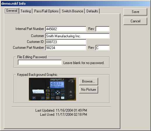
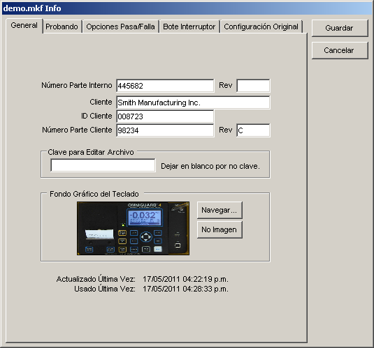
General
This tab contains general file information.
|
- Internal Part Number and Rev, Customer, Customer ID, and Customer Part Number and Rev
-
Internal Part Number and Rev and Customer will appear at the bottom of the main window when
the file is open. All of these fields appear in
job and life cycle test log files and can be included on labels.
- File Editing Password
-
Enter a password here to restrict the ability to edit the file. If this field is not blank,
you will be prompted to enter the password the next time you attempt to open the file in edit mode.
- Keypad Background Graphic
-
You may select a graphic file to be displayed behind the items in the
Keypad File's window. This can be a picture of the actual keypad or any
other JPEG (.jpg), GIF (.gif) or bitmap (.bmp) file. The graphic is saved in
the Keypad File once it has been selected and is displayed actual size. Be
careful not to select a file that is too big as you may run out of memory.
Click "Browse..." to select a new file or "No Picture" if you would like to
remove the previously selected background graphic.
- Last Update and Last Used
These are the dates the Keypad File was last modified and the last time it was used for a job.
|
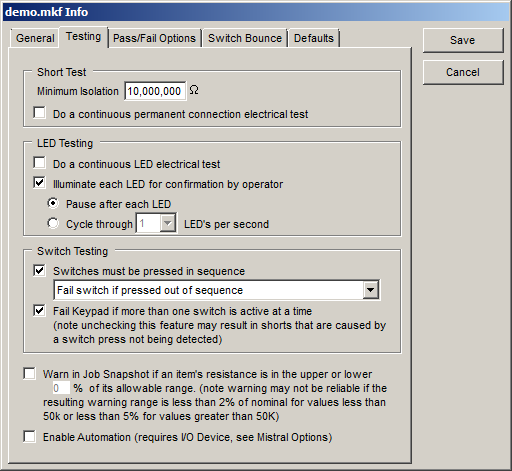
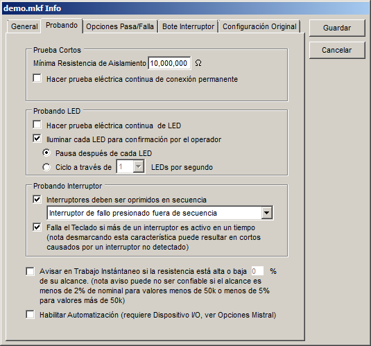
Testing
This tab contains information about how testing is performed.
|
- Short Test
-
- Minimum Isolation Resistance
-
This is the minimum resistance between any two pins that
do not have an LED or permanent connection between them,
including a switch that is not pressed. This is also the minimum
resistance between any pin and any isolation point. During
testing, any resistance paths less than this threshold will be
indicated either in one of the items or in a dialog box. This is
also the maximum resistance allowed for a permanent connection.
Note that only pin numbers that have been assigned to items
will be tested for shorts. If the keypad has any pins or a
shield that are not connected to any switches, LEDs, etc. you
will need to add isolation points for them
if you would like them to be included when checking for
shorts.
- Do a continuous permanent connection electrical test
-
The Mistral tests the permanent connections while looking for shorts. You have the option of
having the resistance of the permanent connections measured repeatedly until you tell it to stop. This may help detect
intermittent connections by allowing the operator to flex the Keypad while testing.
- LED Testing
-
- Do a continuous LED electrical test
-
The Mistral will always electrically test the LEDs. You have the option of
having the forward voltage test run continuously until you tell it to stop. This may help detect
intermittent LED connections by allowing the operator to flex the Keypad while testing.
- Illuminate each LED for confirmation by operator
-
The Mistral always electrically tests each LED on a Keypad. If you would also
like to visually inspect each LED during testing, check "Illuminate each LED for
confirmation by operator".
LED visual inspection can be done in two ways. If "Pause after each LED"
is selected, each LED on the Keypad will be illuminated until you click on
the item or press the space bar. If "Cycle through X LEDs per second" is
selected, each LED is illuminated for a short period of time in sequence.
After all of the LEDs have been illuminated at least once, you can click on
any LED item or press the space bar to advance to the switch test. Click on
the button with the down arrow to select the number of LEDs to illuminate
per second.
Tip: To set the order that LEDs are illuminated use the Set Test Sequence tool.
If "Illuminate each LED for confirmation by operator" is
set to cycle at the "Max" rate, LEDs will be cycled at a high
enough rate to make them appear to all be on. Note that the more
LEDs there are on a keypad, the dimmer they will appear. This feature
requires pod firmware V4.2 or later, which is included with the
software.
- Switch Testing
-
- Switches must be pressed in sequence
-
When this option is checked, the switches must be pressed in the
order indicated by the Test Sequence. The switch that needs to be pressed
next will flash.
Tip: To set the test order when testing switches in
sequence use the Set Test Sequence tool.
Since the Mistral is only looking for one switch at a time when
using this method of testing, it may work better for keypads with
switches interconnected by resistors. Also, using this test method
allows testing of multiple switches that use the same two pins. See Testing Duplicate Switches for more
information.
- Fail switch if pressed out of sequence, Fail Keypad immediately if switch pressed out of sequence, Ignore switches pressed out of sequence
-
When "Switches must be pressed in sequence" is checked you can choose what you would like to happen
when a switch is pressed out of sequence. If "Fail switch if pressed out of sequence" is selected, a switch pressed out of order will
be bad until is is pressed in its proper location in the sequence.
Choosing "Fail Keypad immediately if switch pressed out of sequence" forces the
test to end immediately and the keypad to fail if a switch is pressed out of order.
You can combine this with the "Fail Password" in the "Pass/Fail Options" to require
supervisor approval to continue or to retest the part. Choosing "Ignore switches pressed out of sequence" can help avoid problems
when switches are connected by resistors.
- Fail Keypad if more than one switch is active at a time
-
This item should remain checked unless you have specific problems
testing a keypad. If this item is unchecked, some shorts caused by switch
presses may not be reported.
- Warn In Snapshot
-
When testing, a Job Snapshot showing the results for the last 100 Keypads tested
can be displayed at the bottom of the window. This warning level adds an indication in the
snapshot when a resistance measurement is close to its minimum or maximum allowed value. Note
that resistances inside the warning level are still considered good values and are logged as such.
- Enable Automation
-
The Mistral can accept input from external sources and provide feedback using
a digital I/O card installed in the computer. If this box is checked, the Mistral will attempt
to use Automation when testing. To find out more see Automation.
|
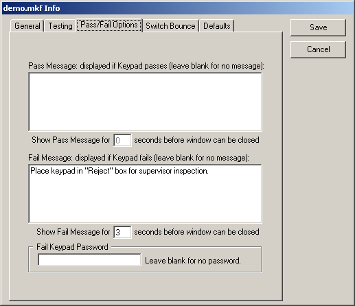
Pass/Fail Options
This tab contains options for what happens after a Keypad has been passed or failed.
|
- Pass Message
-
A window will pop up displaying this message every time the operator passes a Keypad
during testing. If you leave this blank, the window will not be shown.
- Show Pass Message for X seconds before window can be closed
-
If there is a message in the Pass Message field, this number sets the
time in seconds that the operator must wait before the message window can be
closed. If this is set to 0, the Pass Message will still be shown but the
operator can close the window immediately.
- Fail Message
This message will be displayed in the Fail Comments window every time a Keypad is failed during testing.
- Show Fail Message for X seconds before window can be closed
-
If there is a message in the Fail Message field, this number sets the
time in seconds that the operator must wait before the Fail Comments window can be
closed. If this is set to 0, the Fail Message will still be shown but the
operator can close the window immediately.
- Fail Keypad Password
-
If this field is not blank, the password it contains must be entered
in order to continue testing when a part fails. Use this feature if, for example,
the operator must notify quality assurance personnel (who know the
password) when a keypad fails.
|
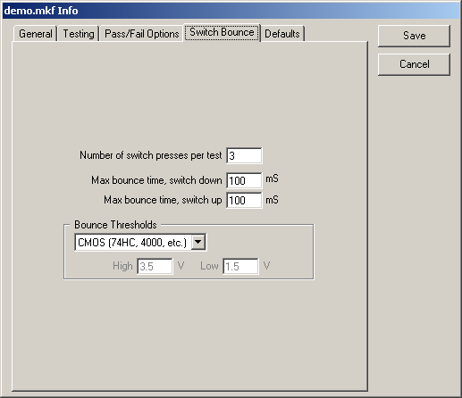
Switch Bounce
This tab contains the switch bounce test setup.
|
- Number of switch presses per test
This is the number of additional times a key must be pressed for the bounce test.
- Max bounce time, switch down and switch up
-
These numbers are the maximum bounce times allowed when pressing and releasing a switch.
If any bounce time measured during the switch bounce test exceeds these times, the switch is
failed.
- Bounce Thresholds
-
The Bounce Thresholds section lets you choose from standard voltage thresholds or set custom
thresholds between 0 and 5 Volts. See Switch Bounce Measurement for
more information on bounce testing.
|
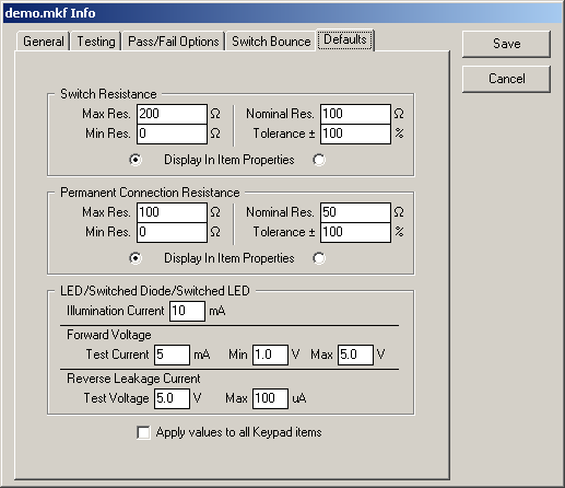
Defaults
This tab contains the default properties for switches, permanent
connections and LEDs. These values are used when an item is created
manually or automatically while learning.
|
- Switch Resistance
-
These are default values for newly created switches. The switch's
resistance characteristics can be defined and viewed as either as a minimum
and maximum allowable resistance or as a nominal resistance and a tolerance.
The two definition methods will always be equivalent. For example, changing
Max Res. will cause Nominal Res. and Tolerance to change.
Important:
Changing these values will change the corresponding property for any switch
item already in the Keypad File if that property was set to the old default
value.
- Max Res.
-
This is the default maximum resistance for each switch created. If the measured switch resistance is
greater than this value, the switch will be considered bad.
- Min Res.
-
This is the default minimum resistance for each switch created. If the measured switch resistance is
less than this value, the switch will be considered bad.
- Nominal Res.
-
This is the default ideal resistance for each switch created. If the measured switch resistance
differs from this value by more than the stated tolerance the switch is considered bad.
- Tolerance
-
This is the default resistance tolerance for each switch created. If the measured switch resistance
differs from the nominal resistance by more than this tolerance the switch is considered bad.
- Display In Item Properties
-
The resistance properties of a switch can be viewed as either Max/Min Res or Nominal Res/Tolerance
in the item properties. Click on the radio buttons on either side of this label to select the
default method of viewing a switch's resistance properties.
-
Permanent Connection Resistance
-
These are default values for newly created permanent connections. The
permanent connection's resistance characteristics can be defined and viewed
as either as a minimum and maximum allowable resistance or as a nominal
resistance and a tolerance. The two definition methods will always be
equivalent. For example, changing Max Res. will cause Nominal Res. and
Tolerance to change.
Important: Changing these values will change the
corresponding property for any permanent connection item already in the
Keypad File if that property was set to the old default value.
- Max Res.
-
This is the default maximum resistance for each permanent
connection created. If the measured permanent connection
resistance is greater than this value, the permanent connection
will be considered bad.
-
Min Res.
-
This is the default minimum resistance for each permanent
connection created. If the measured permanent connection
resistance is less than this value, the permanent connection
will be considered bad.
-
Nominal Res.
-
This is the default ideal resistance for each permanent
connection created. If the measured permanent connection
resistance differs from this value by more than the stated
tolerance the permanent connection is considered bad.
-
Tolerance
-
This is the default resistance tolerance for each
permanent connection created. If the measured permanent
connection resistance differs from the nominal resistance by
more than this tolerance the permanent connection is considered
bad.
-
Display In Item Properties
-
The resistance properties of a permanent connection can
be viewed as either Max/Min Res or Nominal Res/Tolerance in the item
properties. Click on the radio buttons on either side of this
label to select the default method of viewing a permanent
connection's resistance properties.
-
LED/Switched Diode/Switched LED
-
These are default values for newly created LEDs, series LEDs,
Switched Diodes and Switched LEDs.
Important: Changing these values will change the values for items
already in the Keypad File if they are set to the old default value.
- Illumination Current
-
This is the default current used to illuminate the
LED or series LED for visual inspection.
-
Forward Voltage Test Current
-
This is the default value for the amount of current applied to the LED to measure the forward
voltage.
-
Forward Voltage Min
-
This is the default value for minimum forward voltage allowed
across the LED when the Test Current (see above) is applied. If the
forward voltage measured is less than this value the LED is considered
bad. You should leave this value at "1.0" unless your requirements call
for a specific forward voltage for the LEDs.
-
Forward Voltage Max
-
This is the default value for the maximum forward
voltage allowed across the LED when the Test Current
(see above) is applied. If the forward voltage measured
is greater than the maximum the LED is considered bad.
For series LEDs the maximum forward voltage is not
used. You should leave the value at "4.2" unless your
requirements call for a specific forward voltage for the
LEDs.
-
Reverse Leakage Current Test Voltage
-
This is the default for the reverse voltage applied to the LED to
test leakage current.
-
Reverse Leakage Current Max
-
This is the default value for the maximum amount of reverse leakage
an LED can exhibit when the Test Voltage (see above) is applied. If the current
exceeds this value, the LED is considered bad.
-
Apply Values To All Keypad Items
-
If this box is checked, all items that use default values when they are created
will be reset to the default value when "Save" is clicked.
|
|
Item Properties
Each item in the Keypad File (switch, LED, series LED, permanent connection
or isolation point) has properties associated with it. When a new item is added,
either by using the tools or while learning, the initial values for the items
are take from the default values entered in the Edit Info window.
To view and edit an item's properties, choose the Select/Move tool and click
on the item. The properties will be displayed in the properties box in the lower
left corner of the program window and can be editing by clicking in the
appropriate field.
Each item has a Label and From and To Pins (except isolation points which
only have one Pin). An item is not considered ready until all of its pins have been
set, either by entering them in the properties box or automatically while
learning. Items are displayed in color codes which indicate if they are completely
defined.
|
Gray -
|
no pins are assigned
|
|
Blue -
|
some, but not all, of the pins are assigned
|
|
Green -
|
all pins assigned
|
In addition to the Label and the pin numbers all items except isolation points have
additional properties as described below.
|
Switches and Permanent Connections
Switches and permanent
connections both have a resistance that can be specified as
a Max Res and Min Res or Nominal Res and Tolerance. When testing,
the resistance between the From and To pins must be within the specified
range for the item to pass.
To change how a switch or permanent connection's resistance
properties are viewed, click on the down arrow button in the properties
box. You can then choose to view the maximum and minimum resistances or
the nominal resistance and tolerance.
The resistance measured can also be plotted during a test by selecting "Graph While Testing".
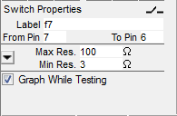
Switch with the resistance specified as maximum and minimum
|
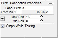
Permanent connection with the resistance specified as resistance and tolerance
|
See Setting Switch And Permanent Connection Resistance for more information
on how to set resistance values to meet your requirements.
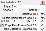
LEDs, Series LEDs, Switched Diodes, Switched LEDs and 7-Segment LEDs
 The color of the LED (with the exception of 7-Segment LEDs)
can be set by clicking on the light bulb icon in the properties window and then selecting the color
from the pop up menu. The color of the LED (with the exception of 7-Segment LEDs)
can be set by clicking on the light bulb icon in the properties window and then selecting the color
from the pop up menu.
LEDs, Series LEDs, Switched LEDs and 7-Segment LEDs have an illumination current used
to light the LED for visual inspection.
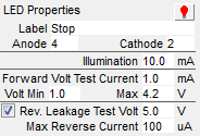
Next, these items have properties for the forward voltage check. The Forward Voltage Test Current (given in mA)
is applied and the voltage must be between the Volt Min and Max. If the voltage
is under the minimum or over the maximum, the item is considered bad. For Series LEDs
there is no maximum forward voltage so the
voltage will be considered good as long as it is greater than the minimum. The
forward voltage properties should be left at their default values unless your
requirements call for a specific forward voltage.
Each item also has several properties for measuring the reverse leakage current. The Test Voltage
is applied in reverse and the item is considered good as long as the leakage current is less than
the Max Reverse Current. To disable the test for reverse leakage, uncheck the box beside the Test Voltage.
This is helpful for LEDs with Zener diodes for protection that tend to have high reverse leakage.
Light Sensors
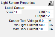 Begin setting up the item by
clicking on the sensor icon in the properties window and selecting the type of
light sensor from the pop up menu. You may choose a two pin phototransistor or photodiode
type sensor or a three pin sensor with voltage or current output. Older Mistrals support
two pin devices only. Begin setting up the item by
clicking on the sensor icon in the properties window and selecting the type of
light sensor from the pop up menu. You may choose a two pin phototransistor or photodiode
type sensor or a three pin sensor with voltage or current output. Older Mistrals support
two pin devices only.
When testing the sensor, the Mistral will apply the Sensor Test Voltage and wait
for the state to go below the Max Dark Current or Voltage when the sensor is covered and then above
the Min Light Current or Voltage when exposed to light.
|
Generating A Keypad File Report
You can generate a report for a keypad file by selecting "Save Info Report As..." from the "File"
menu while the file is open. This report contains all the information in
the Edit Info window as well as the settings for each item in the file.
< | Help Index | >
< | Index de Ayuda | >
|
|
Creando y Editando Archivos Teclado
|
Creando un Nuevo Archivo Teclado
Para crear un nuevo Archivo Teclado seleccione "Nuevo" en el menú "Archivo". Un Archivo
Teclado en blanco aparecerá y la ventana de Editar Info abrirá. Deberá confirmar la
configuración de pruebas y los valores originales antes de seguir.
Nota: Puede cambiar esta
información después seleccionando "Editar Info..." bajo el menú "Editar" o haciendo clic en el botón
Editar Info en el lado izquierdo. Vea Editar Info para más
información.
Abriendo un Archivo Teclado
Para abrir un Archivo Teclado seleccione "Abrir..." bajo el menú "Archivo" o doble clic en el archivo
en el navegador en el lado izquierdo.
Para edita un Archivo Teclado necesita estar en el modo Editar Archivo Teclado. Para entrar este modo
seleccione "Editar Archivo Teclado" bajo el menú "Archivo".
Aprendiendo un Archivo Teclado Automáticamente
El Mistral fue diseñado para facilitar la creación de un nuevo Archivo Teclado. Primero crea un nuevo
archivo. Conected un buen Teclado al pod usando el cable y adaptador incluidos. Puede conectar el teclado
a cualquier pin en el adaptador (menos pins 31 y 32 en un sistema de 30 puntos) pero tiene que asegurar de
conectarlo igual durante pruebas.
Clic en la herramienta Aprender Archivo Teclado (parece a una barra mágica) para empeza a aprender el teclado. Después de
confirmar que tiene el Teclado conectado el sistema automáticamente empieza a aprender, buscando primero por conexiones
permanentes y LEDs. El LED en el panel en el frente parpadeará en rojo (o el LED derecho se pone en rojo si hay dos LEDs)
mientras busca. Si encuentra LEDs se le va a preguntar que confirme el LED está encendido haciendo clic el el objeto gris LED
en la ventana del Archivo Teclado.
Tip: Create
LEDs manual antes de empezar a aprender para que los puedas ubicar donde
quieres. Luego haces clic en el objecto que es igual al que Mistral ha iluminado.
Cuando termine con los LEDs, el panel de frente parpadeará en rojo (o el LED derecho se cambiará a naranja
si hay dos LEDs en frente) y el sistema empezará a escanear por teclas. Oprime una tecla en el Teclado y
sostengalo hasta que el pod haga bip y el cursor cambie a una flecha con pregunta. Luego haga clic en el
interruptor gris que corresponde al teclado oprimido. Repita este proceso para todas las teclas en el
Teclado y luego oprima Parar Aprendizaje.
Durante aprendizaje, el sistem automáticamente agrega artículos para conexiones permanentes,
LEDs o interruptores que encuentra si no hay objetos no usados disponibles. Puedes agregar
artículos antes de aprender (vea abajo) o re-aprender un Archivo Teclado.
Tip: Puedes seleccionar el tamaño de los artículos que serán agregados
automáticamente. Vea Definiendo Manualmente un Archivo Teclado abajo para ver
como seleccionar diferentes tamaños.
A cualquier tiempo durante el proceso de aprender puedes mover artículos haciendo
clic y arrastrandolos o usando las fleshas en el teclado. Tambien puedes editar las
propiedades haciendo clic en el objeto y cambiando la información en la caja de
propiedades (vea Propiedades de Objeto abajo para más información).
Aviso: Si el teclado tiene pins o una covertura que no está conectada a unos interruptores,
LEDs, etc. necesitará añadir puntos de aislamiento para ellos si gusta
que sean incluidos cuando revisando por cortos. Estos tipos de conexiones no pueden ser detectados
durante aprendizaje porque no están conectados eléctricamente conectados.
Definiendo Manualmente un Archivo Teclado
Si un conocido teclado bueno no es disponible o si quiere preparar archivos en una
computadora que no es conectada a Mistral, el Archivo Teclado puede ser definido
manualmente. Adicionalmente unos objetos de teclado, como diodos conmutados
y sensores de luz, no se pueden aprender automáticamente.
Tambien unas configuraciones, como interruptores a traves de LEDs, deben ser parcialmente
entradas manualmente. Puede agregar (interruptores, LEDs, conexiones permanentes, etc.)
para cualquier circuito en el Teclado que quiere probar.
Para seleccionar el tamaño de un objeto antes de añadirlo, haga clic derecho en la herramienta
del objeto. Cuando el menú de tamaños aparezca seleccione el tamaño. Cada tipo puede tener diferentes
tamaños. El tamaño seleccionado tambien se va a usar cuando se agregan objetos durante el proceso
de aprender un Archivo Teclado automáticamente.
Nota: Puede ver el tamaño seleccionado corrientemente moviendo el mouse sobre la herramienta
del objeto. Tambien, puede cambiar el tamaño de un objeto colocado en un Archivo Teclado usando
las herramientas para crecer y encojer detalladas abajo.
Para agregar un artículo, arrastrelo de la área de herramientas a la ventana
del Archivo Teclado o haga clic en la herramienta y luego clic en el Archivo
Teclado. Pueda necesita editar los pins en las Propiedades de Objeto que corresponden
a la conexiones en el Teclado o use la función Prueba Teclado
para agregar números de pin.
Mientras está editando puede mover objetos haciendo clic y arrastrándolos o usando las
flechas en el teclado. Para editar las propiedades del objeto haga clic en el objeto y cambie
la información en la caja de propiedades (vea Propiedades de Objeto abajo
para más información).
Si va a añadir muchos interruptores puede crear un archivo (CSV) para definirlos. El archivo debe contener una
línea por interruptor en el formato "Nombre, De Pin, A Pin, Min Resistencia, Max Resistencia". Para importar, abra
un Archivo Teclado, seleccione "Importar Interruptores..." bajo el menú "Archivo" y escoja el archivo CSV. Los interruptores
van a ser agregados al Archivo Teclado activo. No va a ser verificado por valores correctos o si hay duplicados.
Usando las Herramientas
La área de herramientas contiene una variedad de botones que le permite editar un Archivo Teclado. Las herramientas
son visibles cuando un Archivo Teclado está abierto y el programa está en modo de editar.
|
Herramientas de Aprender/Editar/Gráfica
Las herramientas en el lado izquierdo son para aprender sobre un teclado, editar
las propiedades de un objeto seleccionado o el archivo entero, y para añadir elementos
gráficos.
Seleccionar/Mover
-
Use esta herramienta para seleccionar objetos para moverlos, editarlos or borrarlos. Para mover un
objeto, línea o texto, haga clic y arrastrelo con esta herramienta or haga clic en el y muevalo usando
las flechas en el teclado. Para edita un objeto, use esta herramienta para seleccionarlo y luego comience
editar la información en la caja de propiedades. Para borrar un objeto, línea o texto, haga clic
luego oprima la tecla "Delete" o seleccione "Borrar" bajo el menú "Editar". Puede sleccionar varios
objetos para mover, cambiar el tamaño o borrarlos oprimiendo el botón izquierdo y arrastrando el
mouse sobre los objetos que quiere seleccionar. Tambien puede seleccionar varios objetos oprimiendo
la tecla Shift y haciendo clic en cada objeto.
Aprender Archivo Teclado
-
Haga clic en esta herramienta para aprender un Archivo Teclado. Vea Aprendiendo un Archivo Teclado Automáticamente
arriba para más información.
Probar Teclado
-
Haciendo clic en esta herramienta te permite encontrar el número de pin de un punto
en el adaptador para su Teclado. Esto ayuda cuando tiene un adaptador con densidad alta
o una fijación personalizada y necesita figurar como se traduce un pin en el Mistral
a un pin en su Teclado. Necesitará conectar un clip de prueba a uno de los conectores
pala en el adaptador (el software te dirá cual).
Cuando pruebas un pin, el número de pin aparecerá abajo y a la derecha del cursor del
mouse. Si tiene objetos en el Archivo Teclado que no tienen pins asignados, puede hacer
clic en el objeto para añadir ese pin al objeto.
Establece Secuencia de Prueba
-
Haga clic en esta herramienta para fijar el orden que los LEDs e interruptores son probados. Para LEDs
la Secuencia de Prueba es el orden en que son iluminados si "Iluminar cada LED para confirmación por
el operador" es seleccionado bajo el tab Probandoen la ventana Editar Info. Para interruptores la Secuencia
de Prueba es el orden en que los interruptores deben ser oprimidos si "Interruptores deben ser oprimidos en
secuencia" es seleccionado bajo el tab Probandoen la ventana Editar Info.
Para fijar la Secuencia de Prueba haga clic en los LEDs e interruptores en el orden que gusta
probarlos. Después de seleccionar un objeto, su número de Secuencia de Prueba aparecerá en la
derecha superior en la gráfica del objeto. Solamente puede fijar la Secuencia de Prueba para LEDs
e interruptores.
Cuando termines fijando la Secuencia de Prueba oprima "Para Establecer Secuencia". Cualquier LED
o interruptor que no tiene un número de Secuencia de Prueba cuando "Para Establecer Secuencia" es
oprimido va a tener su número asignado automáticamente.
Para ver la Secuencia de Prueba a cualquier tiempo, seleccion "Mostrar Secuencia de Prueba" bajo el menú "Archivo".
Editar Info
-
Haciendo clic en esta herramienta abre la ventana Editar Info (tambien la puede abrir seleccionando
"Edita Info..." bajo el menú "Editar"). Esta ventana contiene varias configuraciones originales para
el Archivo Teclado. Aqui es donde fijas el valor original para la resistencia máxima para los interruptores
y corriente de prueba para LEDs y la mínima resistencia de aislamiento. Estos valores deben ser
fijados antes de agregar objetos al Archivo Teclado o use la herramienta Aprender Archivo Teclado. Vea
Editar Info abajo para más información.
Crecer Objeto
-
Haga clic en esta herramienta para crecer el tamaño del objeto seleccionado. Tambien
puede crecer el objeto seleccionando "Crecer" bajo el menú "Editar" u oprimiendo Ctrl+G.
Encoger Objeto
-
Haga clic en esta herramienta para encoger el tamaño del objeto seleccionado. Tambien
puede encoger el objeto seleccionando "Encoger" bajo el menú "Editar" u oprimiendo Ctrl+K.
Dibujar Línea
-
Haga clic en esta herramienta para dibujar líneas en el Archivo Teclado. Líneas son para ayudar en
orientar el Teclado durante pruebas y no representan conexiones eléctricas.
Para dibujar una línea, seleccione esta herramienta y haga clic en la ventana del Archivo Teclado
donde va a comenzar la línea. Una pequeña "+" aparecerá. Luego haga clic donde quiere terminar la
línea. Líneas siempre son horizontales o verticales y siempre se ajustan a la cuadrícula.
Añadir/Editar Texto
-
Seleccione esta herramienta para añadir texto al Archivo Teclado o para edita el texto existente. Esto
se puede usar para añadir notas como posiciones del conector o la orientación del Teclado.
Para agregar texto, seleccione esta herramienta y haga clic en la ventana del Archivo Teclado donde gusta
tener texto. Una caja pequeña aparecerá. A medida que escribe la caja se ajusta para encapsular el texto.
Para editar texto existente, seleccione esta herramienta y haga clic dentro de la caja de texto que gusta editar.
|
|
Herramientas para Añadir Objetos
Las herramientas en el lado derecho son para añadir objetos a un Archivo Teclado. Un objeto es una
representación de algo en el teclado que se puede probar eléctricamente. Para añadir un objeto, haga
clic la herramienta y arraste a la ventana del Archivo Teclado o haga clic la herramiento luego haga
clic en la ventana del Archivo Teclado. Puede seleccionar el tamaño antes de agregar el objeto oprimiendo
y sosteniendo la herramienta hasta que el menú de tamaños aparezca y luego seleccionando el tamaño.
Interruptor
- Un interruptor es un objeto que conecta dos pins momentáneamente y es definido por su resistencia.
LED
-
Un LED puede ser agregado para iluminar el LED correspondiente en el teclado y tambien para probar
sus características eléctricas.
Tip: Si estás en el modo de editar y haces clic
en un LED que tiene sus pins asignados correctamente y tiene un Mistral y
un Teclado conectados, el LED va a ser iluminado en el Teclado por un corto
tiempo. Tambien, puede mover el mouse sobre el objeto para ver el voltaje a
traves del LED cuando la Corriente de Prueba para Voltaje Delantero es aplicada.
LED Serie
-
Un LED en serie son dos o más LEDs conectados en serie en el Teclado. Tambien puede ser
un LED con un resistor en serie resultando en un voltaje delantero alto. Este objeto
solamente debe ser usado cuando tienes una configuración de LEDs donde el voltaje
delantero va a ser más de 15V. El Mistral no siempre puede detectar y probar este tipo de
configuración. Definiendo un objeto de LED serie puede seguir iluminando los LEDs
como parte de la prueba. Debe definir objetos de LED serie manualmente porque el Mistral
no los detecta. Use este objeto si después de aprender un Teclado, LEDs conectados en
serie no fueron detectados.
Tip: Si estás en el modo de editar y haces clic
en un LED serie que tiene sus pins asignados correctamente,
el LED va a ser iluminado en el Teclado por un corto tiempo.
Aviso: El operador debe asegurar que los LED serie
iluminan durante una prueba; el Mistral puede no ser capaz
de probarlos eléctricamente.
Monitor 7-Segmentos
-
Agregando un monitor 7-segmentos agrega 7 segmentos individuales más un LED pequeño
para el punto decimal. Estos segmentos son iluminados y probados como LEDs individuales.
El Mistral no crea un monitor 7-segmentos automáticamente cuando está aprendiendo pero
puede seleccionar segmentos colocados en avance. Antes de comenzar a aprender, agrega un
monitor 7-segmentos para cada uno en el teclado. Asegure que hay suficientes LEDs normales
para cada LED regular. El Mistral cuando está aprendiendo automáticamente va a iluminar
cada LED que encuentra y debes hacer clic el segmento o LED correspondiente.
Tip: Igual como los otros LEDs, si estás en modo de editar y haces clic end un
segmento, el LED en el Teclado va a ser iluminado por un corto tiempo. Después
de esto, puedes mover el mouse sobre el objeto y ver el voltaje a traves del LED
cuando la Corriente de Prueba de Voltaje Delantero es aplicada.
Conexión Perm.
-
Una conexión permanente representa dos pins que siempre están conectados. Puede ser
una traza o un resistor.
Diodo Conmutado
-
Un diodo conmutado es un interruptor en serie con un diodo donde la conexión entre el interruptor
y el diodo no es disponible en el conector del teclado. El operador prueba este objeto como un
interruptor pero es probado eléctricamente como un LED. Un diodo conmutado no se puede aprender
pero puede aparecer como un interruptor normal (con resistencia alta) durante aprendizaje. Debe
agregar diodos conmutados manualmente después de aprender un teclado.
LED Conmutado
-
Para describir un interruptor en serie con un LED donde la conexión entre el interruptor y el LED
no es disponible en el conector del teclado, use un LED conmutado. El operador prueba este objeto
como un interruptor pero es probado eléctricamente como un LED. El operador puede ver como
el LED se va a ver cuando la corriente de iluminación pasa a traves de el oprimiendo el interruptor.
Un LED conmutado no se puede aprender pero puede aparecer como un interruptor normal (con resistencia alta)
durante aprendizaje. Debe agregar LEDs conmutados manualmente después de aprender un teclado.
Tip: Igual como los otros LEDs, si estás en modo de editar y haces clic en el
LED conmutado mientra oprimas el interruptor, el LED va a ser iluminado por
corto tiempo. Después de esto, puedes mover el mouse sobre el objeto y ver el voltaje a traves del LED
cuando la Corriente de Prueba de Voltaje Delantero es aplicada.
Punto Aislamiento
-
Un punto de aislamiento representa un pin individuo en el conectador del pod que gustes
sea revisado contra todos los otros pins en el Archivo Teclado aunque no esté conectado
a interruptores, LEDs o conexiones permanentes. Puedes usas esto para asegurar un pin no
usado no esté haciendo un corto con otro pin o como un punto de conexión para una covertura
en el Teclado que debe ser aislado de todas las conexiones. Puntos de aislamiento deben ser
agregados manualmente; no son detectados durante aprendizaje porque no están conectados
eléctricamente a otros pins.
Sensor Luz
-
El sensor luz permite probar componentes que reaccionan a luz. Para probar, el operador cubre y descubre
el sensor mientras el Mistral mide sus características eléctricas. Fotodiodos con dos terminalesy fototransistores y circuitos
integrados con tres terminales con salidas de corriente o voltaje pueden ser probados con el último Mistral. Con software anterior a la versión v4.20 puede probar
sólamente dispositivos con dos terminales.
Aviso: Sensores luz no pueden ser aprendidos automáticamente. Si el teclado contiene un sensor luz debe ser
agregado manualmente antes de comenzar a aprender un teclado.
|
Ventana Editar Info
La ventana de Editar Info contiene ajustes que aplican al Archivo Teclado. Abre la ventana seleccionando la
ventana del archivo y luego "Editar Info" bajo el menú "Editar" o haciendo clic en el botón Editar Info.
La ventana Editar Info es organizada en cuatro tabs. Haga clic en el nombre del tab para ver ese tab.
|
General
Este tab contiene informacón general del archivo.
|
- Número Parte Interno y Rev, Cliente, ID Cliente, and Número Parte Cliente y Rev
-
Número Parte Interno y Rev y Cliente aparecen en el fondo de la ventana principal cuando el
archivo es abierto. Todos estos campos aparecen en logs de trabajo y pruevas de ciclo de vida
y pueden ser incluidos en etiquetas.
- Clave para Editar Archivo
-
Entre una clave para limitar la abilidad de editar un archivo. Si este campo no es blanco,
se le pedirá entrar la clave la siguiente vez que trate de abrir el archivo para editar.
- Fondo Gráfico del Teclado
-
Puede seleccionar un archivo gráfico para mostrar detrás de objetos en la ventana
del Archivo Teclado. Esto puede ser una foto del teclado actual o cualquier
archivo JPEG (.jpg), GIF (.gif) o bitmap (.bmp). La gráafica es guardada en el Archivo
Teclado una vez que sea seleccionada y es mostrada en tamaño actual. Cuidado de no
seleccionar un archivo muy grande como usted puede usar toda la memoria. Haga clic
"Navegar..." para seleccionar un nuevo archivo o "No Imagen" si quiere remover la
gráfica previamente seleccionada.
- Actualizado Última Vez y Usado Última Vez
Estas son las fechas que el Archivo Teclado fue modificado y la última vez que fue usado para un trabajo.
|
Probando
Este tab contiene información sobre como se hacen las pruebas.
|
- Prueba Cortos
-
- Mínima Resistencia de Aislamiento
-
Esta es la mínima resistencia entre dos pins que no tienen un
LED o conexión permanente entre ellos, incluyendo un interruptor
no oprimido. Esta tambien es la mínima resistencia entre un pin
y un punto de aislamiento. Durante una prueba, cualquier camino de
resistencia menos de este valor va a ser indicado en uno de los objetos
o en un diálogo. Tambien es la máxima resistencia permitida para una
conexión permanente.
Nota que solamente números de pin que se han asignado a objetos
van a ser probados por cortos. Si el teclado tiene unos pins o
una covertura que no están conectados a interruptores, LEDs, etc.
necesitarás agregar puntos de aislamiento
para ellos si gustas incluirlos cuando esté revisando por cortos.
- Hacer prueba eléctrica continua de conexión permanente
-
El Mistral prueba conexiones permanentes mientras busca por cortos. Tiene la opción de
medir la resistencia de la conexión permanente continuamente hasta que le digas que pare.
Esto puede ayudar a detectar conexiones intermitentes por permitiendo al operador flexionar
el Teclado durante pruebas.
- Probando LED
-
- Hacer prueba eléctrica continua de LED
-
El Mistral siempre prueba eléctricamente los LEDs. Tiene la opción de
correr la prueba de voltaje delantero continuamente hasta que le digas
que pare. Esto puede ayudar en detectar conexiones de LED intermitentes
por permitiendo al operador flexionar el Teclado durante pruebas.
- Iluminar cada LED para confirmación por el operador
-
El Mistral siempre prueba eléctricamente cada LED en un Teclado. Si gusta inspeccionar
cada LED visualmente durante pruebas, seleccione "Iluminar cada LED para confirmación por
el operador".
Inspección visual de cada LED se puede hacer en dos maneras. Si "Pausa después
de cada LED" es seleccionado, cada LED en el Teclado va a ser iluminado hasta
que haga clic en el objeto u oprima la barra espaciadora. Si "Ciclo a través de
X LEDs por segundo" es seleccionado, cada LED es iluminado por un corto tiempo en
secuencia. Después que todos los LEDs han sido iluminados por menos una vez, puede
hacer clic en un objeto LED u oprimir la barra espaciadora para avanzar a la prueba
de interruptores. Haga clic en el botón con la flecha para seleccionar el número de
LEDs para iluminar por segundo.
Tip: Para fijar el orden que los LEDs son iluminados use la herramienta Fijar Secuencia de Prueba.
Si "Iluminar cada LED para confirmación por el operador" es fijado que cicle a la
"Max" velocidad, los LEDs van a ser ciclado en una velocidad suficientemente alta
que aparecen todos estar iluminados. Nota que en que más LEDs esten en el teclado,
lo más oscuro aparecerán. Esta característica requiere el firmware de pod V4.2 o
más tarde, que es incluida con el software.
- Probando Interruptor
-
- Interruptores deben ser oprimidos en secuencia
-
Cuando esta opción es seleccionada, los interruptores deben ser oprimidos en el
orden indicado por la Secuencia de Prueba. En interruptor que debe ser oprimido
al siguiente parpadeará.
Tip: Para fijar el orden de los interruptores durante pruebas use
la herramienta Fijar Secuencia de Prueba.
El Mistral solamente busca por un interruptor a la vez cuando se usa
este método de pruebas, es posible funcione mejor para teclados con
interruptores conectados por resistores. Tambien, usando este método
de pruebas permite probar varios interruptores que usan los mismos dos
pins. Vea Probando Interruptores Duplicados
para más información.
- Interruptor de fallo presionado fuera de secuencia,Falla Teclado inmediatamente si interruptor fuera de secuencia,Ignorar los interruptores presionados fuera de secuencia
-
Cuando "Interruptores deben ser oprimidos en secuencia" es seleccionado, exta opción
forza la prueba que termine inmediatamente y el teclado falla si un interruptor es
oprimido fuera de orden. Puede combinar esto con "Clave de Falla" bajo "Opciones
Pasa/Falla" para requerir la aprobación del supervisor para continuar o tratar de probar
la parte de nuevo.
- Falla el Teclado si más de un interruptor es activo en un tiempo
-
Esta opción debe de estar seleccionada al menos que tenga problemas específicos
probando teclados. Si no está seleccionada, unos cortos causados por interrupciones
pueden no ser reportados.
- Avisar en Trabajo Instántaneo
-
Durante pruebas, un Trabajo Instántaneo muestra los resultados de los últimos
100 Teclados probados puede ser mostrado en el fondo de la ventana. Este nivel de aviso da una indicación
instantanea cuando la resistencia medida es cercas a su min o max permitido. Nota que resistencias dentro
del nivel de aviso son consideradas valores buenas y son grabadas asi.
- Habilitar Automatización
-
El Mistral puede acceptar entradas de fuentes externas y proveer feedback usando una tarjeta
I/O digital instalada en la computadora. Si esta opción es seleccionada, el Mistral va a tratar
de usar Automatización durante pruebas. Para ver más vea Automatización.
The Mistral can accept input from external sources and provide feedback using
a digital I/O card installed in the computer. If this box is checked, the Mistral will attempt
to use Automation when testing. To find out more see Automatización.
|
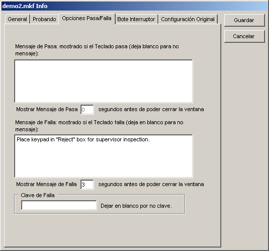
Opciones Pasa/Falla
Este tab contiene opciones para decidir que hacer si falla o pasa el Teclado.
|
- Mensaje de Pasa
-
Una ventana aparecerá mostrando este mensaje cada vez que el operador pasa un Teclado
durante pruebas. Si lo deja en blanco, la ventana no se mostrará.
- Mostrar Mensaje de Pasa X segundos antes de poder cerrar la ventana
-
Si hay un mensaje en el campo Mensaje de Pasa, este número fija el tiempo en
segundos que el operador debe esperar antes que la ventana se pueda cerrar. Si la alerta
es fijada a 0, el Mensaje de Pasa va a ser mostrado pero el operador puede cerrar
la ventana inmediatamente.
- Mensaje de Falla
Este mensaje se mostrará en la ventana de Comentarios de Falla cuando el Teclado es fallado durante pruebas.
- Mostrar Mensaje de Falla X segundos antes de poder cerrar la ventana
-
Si hay un mensaje en el campo Mensaje de Falla, este número fija el tiempo en
segundos que el operador debe esperar antes que la ventana se pueda cerrar. Si la alerta
es fijada a 0, el Mensaje de Falla va a ser mostrado pero el operador puede cerrar
la ventana inmediatamente.
- Clave de Falla
-
Si este campo no es blanco, la clave debe ser entrada para poder continuar
probando cuando la parte falla. Use esta característica si por ejemplo, el
operador debe notificar personal de QA (quien saben la clave) cuando falla
el teclado.
|
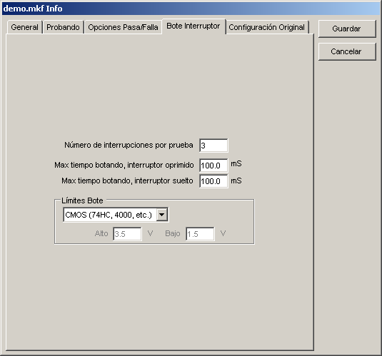
Bote Interruptor
Este tab contiene los ajustes para los botes de interruptor.
|
- Número de interrupciones por prueba
Este es el número de veces que un interruptor debe ser oprimido para la prueba de botes.
- Max tiempo botando, interruptor oprimido y suelto
-
Estos números son el max tiempo permitido cuando oprimiendo y soltando un interruptor.
Si el tiempo en bote medido durante pruebas es más alto, el interruptor falla.
- Límites Bote
-
Los Límites Bote les permiten escoger límites estandard de voltaje o usar un límite personalizado
entre 0 y 5 Volts. Vea See Medidas de Bote de Interruptor para más
información.
|
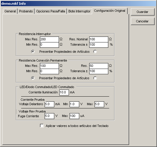
Configuración Original
Este tab contiene los valores de configuración original para interruptores, conexiones
permanentes y LEDs. Estos valores son usados cuando un objeto es creado manualmente o
automáticamente.
|
- Resistencia Interruptor
-
Estos son valores de configuración original para interruptores nuevamente creados.
Las características de resistencia para el interruptor son definidas y vistas como
un min o max resistencia permitida o como resistencia nominal y tolerancia. Los dos
métodos de definir siempre son equivalentes. Por ejemplo, cambiando la Max Res. causa
cambios en la Res. Nominal y Tolerancia.
Importante:
Cambiando estos valores cambia la propiedad correspondiente para cualquier interruptor
ya en el Archivo Teclado si las propiedades eran fijadas al valor viejo.
- Max Res.
-
Este es el valor de configuración original max de resistencia para cada interruptor creado. Si la resistencia
del interruptor medida es más alta que este valor, el interruptor es considerado malo.
- Min Res.
-
Este es el valor de configuración original min de resistencia para cada interruptor creado. Si la resistencia
del interruptor medida es menos que este valor, el interruptor es considerado malo.
- Res. Nominal
-
Este es el valor de configuración original ideal de resistencia para cada interruptor creado. Si la resistencia
del interruptor medida es diferente a este valor por más de la tolerancia, el interruptor es considerado malo.
- Tolerancia
-
Este es el valor de configuración original de la tolerancia de resistencia para cada interruptor creado. Si
la resistencia del interruptor medida es diferente a la resistencia nominal por más de la tolerancia, el interruptor es considerado malo.
- Presentar Propiedades de Artículos
-
Las propiedades de resistencia de un interruptor pueden se vistas como Max/Min Res o Res Nominal/Tolerancia
en las propiedades del artículo. Haga clic en los botones en la derecha o izquierda para seleccionar el método
para presentar las propiedades de resistencia.
-
Resistencia Conexión Permanente
-
Estos son los valores de configuración original para conexiones permanentes nuevamente creadas. Las características
de la resistencia de la conexión permanente pueden ser definidas y vistas como un min y max resistencia permitida
o como resistencia nominal y tolerancia. Los dos métodos de definir siempre son equivalentes. Por ejemplo, cambiando la Max Res. causa
cambios en la Res. Nominal y Tolerancia
Importante:
Cambiando estos valores cambia la propiedad correspondiente para cualquier conexión permanente
ya en el Archivo Teclado si las propiedades eran fijadas al valor viejo.
- Max Res.
-
Este es el valor de configuración original max de resistencia para cada conexión permanente creada. Si la resistencia
de la conexión permanente medida es más alta que este valor, la conexión permanente es considerada mala.
-
Min Res.
-
Este es el valor de configuración original min de resistencia para cada conexión permanente creada. Si la resistencia
de la conexión permanente medida es menos que este valor, la conexión permanente es considerada mala.
-
Nominal Res.
-
Este es el valor de configuración original ideal de resistencia para cada conexión permanente creada. Si la resistencia
de la conexión permanente medida es diferente a este valor por más de la tolerancia, la conexión permanente es considerada mala.
-
Tolerancia
-
Este es el valor de configuración original de la tolerancia de resistencia para cada conexión permanente creada. Si
la resistencia de la conexión permanente es diferente a la resistencia nominal por más de la tolerancia, la conexión permanente es considerada mala.
-
Presentar Propiedades de Artículos
-
Las propiedades de resistencia de una conexión permanente pueden se vistas como Max/Min Res o Res Nominal/Tolerancia
en las propiedades del artículo. Haga clic en los botones en la derecha o izquierda para seleccionar el método
para presentar las propiedades de resistencia.
-
LED/Diodo Conmutado/LED Conmutado
-
Estos son los valores de configuración original para LEDs, LEDs serie, Diodos Conmutados
y LEDs Conmutados nuevamente creados.
Importante: Cambiando estos valores cambiará los valores de los objetos
ya colocados en el Archivo Teclado si las propiedades eran fijadas al valor viejo.
- Corriente Iluminación
-
Este es el valor de configuración original para la corriente usada para iluminar el LED o LED serie para inspección visual.
-
Corriente Prueba Voltaje Delantero
-
Este es el valor de configuración original para la cantidad de corriente aplicada al LED para medir el voltaje delantero.
-
Voltaje Delantero Min
-
Este es el valor de configuración original para el min voltaje delantero permitido a traves del LED cuando una Corriente de Prueba
(vea arriba) es aplicada. Si el voltaje delantero medido es menos que este valor el LED es considerado malo. Debe dejar el valor a
"1.0" solo que sus requisitos especifican un valor de voltaje delantero diferente.
-
Voltaje Delantero Max
-
Este es el valor de configuración original para el max voltaje delantero permitido a traves del LED cuando una Corriente de Prueba
(vea arriba) es aplicada. Si el voltaje delantero medido es más alto que este valor el LED es considerado malo. Debe dejar el valor a
"4.2" solo que sus requisitos especifican un valor de voltaje delantero diferente.
-
Voltaje Rev Prueba Fuga Corriente
-
Este es el valor de configuración original para el voltaje reverso aplicado al LED
para probar la fuga de corriente.
-
Fuga Corriente Max
-
Este es el valor de configuración original para la max fuga de corriente un LED puede exhibir
cuando el voltaje reverso de prueba (vea arriba) es aplicado. Si la corriente es más alta que
este valor, el LED es considerado malo.
-
Aplicar valores a todos artículos del Teclado
-
Si esta opción es seleccionada, todos los objetos ya creados usarán estos valores cuando haga clic en "Guardar".
|
|
Propiedades de Objeto
Cada objeto en el Archivo Teclado (interruptor, LED, LED serie, conexión permanente o punto de aislamiento)
tiene propiedades asociadas con el. Cuando un nuevo objeto es creado, usando las herramientas o aprendiendo,
los valores iniciales para los objetos son tomados de los valores de configuración original entrados en la
ventana de Editar Info.
Para ver y editar las propiedades de un objeto, use la herramienta Selección/Mover y haga clic en el objeto.
Las propiedades van a ser mostradas en la caja de propiedades en el fondo izquierdo de la ventana y pueden ser
editadas haciendo clic en el campo apropiado.
Cada objeto tiene una Etiqueta y De y Al Pin (menos puntos de aislamiento que solo tienen un pin). Un objeto no es
considerado listo hasta que todos sus pins son asignados manualmente o automáticamente durante aprendizaje. Objetos
son mostrados usando códigos de color que indican si están completamente definidos.
|
Gris -
|
no pins asignados
|
|
Azul -
|
unos, pero no todos los pins asignados
|
|
Verde -
|
todos pins asignados
|
Adicionalmente todos los objetos menos puntos de aislamiento contienen propiedades adicionales como descrito abajo.
|
Interruptores y Conexiones Permanentes
Interruptores y conexiones permanentes tienen una resistencia que puede ser especificada como Max Res y Min Res o
Res Nominal y Tolerancia. Cuando probando, la resistencia entre el pin De y Al deben estar entre los límites para
pasar.
Para cambiar como mostrar las resistencias de un interruptor o conexión permanente, haga clic en la flecha dentro
la caja de propiedades. Ahora puede escoger como ver la resistencias max y min o nominal y tolerancia.
La resistencia medida se puede graficar durante la prueba si selecciona "Trazar Durante Prueba".
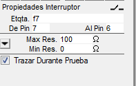
Interruptor con la resistencia especificada como max y min
|
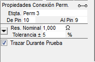
Conexión permanente con la resistencia especificada como nominal y tolerancia
|
Vea Ajustando Resistencia de Interruptor y Conexión Permanente para más información en como
ajustar los valores de resistencia.
LEDs, LEDs Serie, Diodos Conmutados, LEDs Conmutados y Monitor 7-Segmentos
 El color del LED (menos el Monitor 7-Segmentos)
se puede fijar haciendo clic en el foco en las propiedades y luego seleccionando el color en el menú. El color del LED (menos el Monitor 7-Segmentos)
se puede fijar haciendo clic en el foco en las propiedades y luego seleccionando el color en el menú.
LEDs, LEDs Serie, LEDs Conmutados y Monitor 7-Segmentos tienen una corriente de iluminación
usada para iluminar el LED para inspección visual.
Estos objetos tienen propiedades para revisar el voltaje delantero. La Corriente de Prueba para Voltaje Delantero (en mA)
es aplicada y el voltaje debe ser entre el Volt Min y Max. Si el voltaje es menos que el min o sobre el max, el objeto es
considerado malo. Para LEDs Serie no hay voltaje delantero max y el voltaje es considerado bueno mientras es sobre el min.
Las propiedades del voltaje delantero deben ser dejadas a su valor inicial solo que sus requisitos tengan un valor diferente.
Cada objeto tiene varias propiedades para medir la fuga de corriente reversa. El voltaje de prueba es aplicado en reverso
y el objeto es considerado bueno mientras la fuga de corriente sea menos que la Max Corriente Rev. Para desactivar la prueba
de fuga inversa, desactive la casilla de verificación situada junto a al Voltaje de Prueba.
Esto es útil para los LED con diodos zener para la protección que suelen tener alta fuga inversa.
Sensor Luz
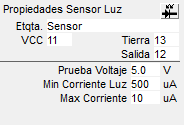 Empieze ajustando el objeto haciendo clic en el icono del sensor en la caja de propiedades y seleccionando el tipo de
sensor en el menú. Puede elegir una de dos clavijas
tipo fotodiodo o fototransistor sensor o un sensor de tres patillas con salida de tensión o corriente. Soporte Mistrals antiguos
sólo dispositivos de dos clavijas.
Empieze ajustando el objeto haciendo clic en el icono del sensor en la caja de propiedades y seleccionando el tipo de
sensor en el menú. Puede elegir una de dos clavijas
tipo fotodiodo o fototransistor sensor o un sensor de tres patillas con salida de tensión o corriente. Soporte Mistrals antiguos
sólo dispositivos de dos clavijas.
Cuando probando un sensor, el Mistral aplica el Voltaje de Prueba Sensor y espera que la corriente baje menos
que la Max Corriente Oscura cuando el sensor es cubierto y luego suba arriba de Min Corriente Luz cuando expuesto
a la luz.
|
Generando un Reporte para el Archivo Teclado
Puede generar un reporte para un Archivo Teclado seleccionando "Guarde Reporte Info Como..." bajo el
menú "Archivo" mientras el archivo está abierto. Este reporte contiene toda la información en la
ventana Editar Info y tambien los ajustes para cada objeto en el archivo.
< | Index de Ayuda | >