< | Help Index | >

|
Life Cycle Testing
|
Life Cycle Test Mode
Life Cycle Testing allows you to log the resistance characteristics for multiple switch
cycles (press and release). In order to perform life cycle testing you must be in the
Life
Cycle Test
mode. Select "Life Cycle Test" from the "File" menu.
Note that switch bounce
measurement can not be done during Life Cycle Testing.
Starting Life Cycle Testing
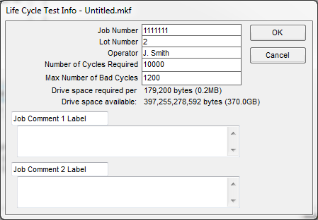
Each life cycle test has an associated job number, lot number, operator (the
person doing the testing) and number of switch cycles required.
To begin a life cycle testing, open a Keypad File while in Life Cycle Test mode. To open a file double click on the file
name in the file browser on the left of the main window or select "Open..." from the "File" menu.
If a file is already open, be sure "Life Cycle Test" is checked in the "File" menu.
With a Keypad File open, click the "Start Life Cycle Test" button. The Life Cycle Test Info window, where you
enter information about the test you are about to begin, will open.
|
- Job Number, Lot Number and Operator
-
These fields are saved as part of the test logs. The Job and Lot Numbers are also used as the
default file names for logs.
- Number of Cycles Required
-
Entering a number will allow the Mistral to notify the operator when a switch has been cycled the required
number of times. You will also be able to see how much disk space is required for each switch tested.
- Max Number of Bad Cycles
-
Entering a number will allow the Mistral to notify the operator when a switch has been cycled the required
number of times. You will also be able to see how much disk space is required for each switch tested.
- Comment Labels and Comments
-
These fields allow you to enter comments that will appear in the
job logs. These fields are also saved in the Keypad File when a job
is completed so they will be there the next time you open the file
for testing. Use the label to identify what is in the comment field or
to prompt the operator for information to
enter in the comment before testing. If you leave both the
label and the comment blank, these fields will not appear in the job
logs.
|
When you have finished with the Life Cycle Test Info window click "OK" to begin the job or "Cancel" to stop.
Life Cycle Testing Switches
To begin life cycle testing a part, connect a Keypad to the pod and click "Test Life Cycle Keypad".
The Mistral begins by performing the normal Keypad test sequence. First the
Mistral scans for shorts between all points used by the Keypad File, including
any isolation points. The LED on the front panel will flash red (or the right LED will turn red if there
are two LEDs on the panel)
while this scan is being done. If a short is found the pod emits a warbling sound and
the error is displayed.
After looking for shorts the Mistral checks permanent connections. If
a permanent connection is good, the connection's item turns green. If it
is bad the item turns red and the pod emits a warbling sound.
Once the permanent connections have been tested the Mistral looks
for LEDs. If LEDs are found they are illuminated one at a time or in
sequence depending on the "LED Test Mode" setting (see Edit Info window for more information). You will
be prompted to click on the LED item to confirm it is lit.
Warning:
If the file contains any series LED items, the operator MUST confirm
that the LEDs illuminate since the Mistral may not be able to test
them electrically.
If an LED is not found or installed backwards,
the corresponding LED item will turn red and the pod emits a warbling
sound. Good LED items will turn green.
Tip: You can press the space
bar to confirm an LED is on.
After completing any LED tests, the LED on the front panel will flash red (or the right LED will turn green or orange if there
are two LEDs on the panel). The Mistral is now ready to begin life cycle testing the switches.
Each time a switch on the Keypad is pressed the pod will beep. On the
PC screen the corresponding switch item will turn yellow (or red) and
the switch resistance will be displayed. The resistance is also saved
for use in the Life Cycle Test Log (see below).
When a switch is released the corresponding switch item will turn
green if the switch is good, red if there was a problem during this switch
cycle or orange if there was a problem during any previous switch cycle.
If the switch resistance after it is released is less than the minimum
isolation resistance specified in the Keypad file's Edit Info window, the switch item will turn red and
the release resistance will be displayed and saved for use in the Life
Cycle Test Log (see below).
To find out why an item is red, position the mouse pointer over it. A box will pop up telling you what
the problem was.
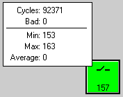
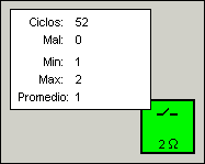
After a switch cycle (press and release) a small window will pop up
beside the switch indicating the number of times the switch has been
pressed, the number of times it was bad (down resistance too high or
release resistance too low) and the minimum,
maximum and average resistance. Note the minimum, maximum and average
resistance includes all switch presses, including those where the
resistance was greater than the maximum specified in the item properties.
If the Number of Cycles Required was entered in the Life Cycle Test Info window
at the start of the test, the word "Done" will appear at the bottom of the pop up
window after the required number of cycles have been completed. "Done" will also appear
if Max Number Bad Cycles is reached.
Finishing The Test And Logging The Results
When you are finished testing click on the "End Life Cycle Test" button.
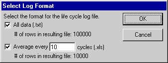
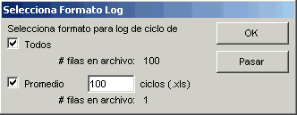
If you have pressed at least one switch, you will be asked to
select the Life Cycle Test Log File format. You can create a file
containing resistance information for each switch cycle or one with
an average for every so many cycles.
|
- All Data (.txt)
-
This log format contains the information entered in the Life Cycle Test Info, a
summary of the information for each switch on the Keypad and the resistance information
for each switch cycle. The resistance information is saved in a tab delimited
format.
- Average every X cycles (.xls)
-
This format also contains the information entered in the Life
Cycle Test Info, a summary of the information for each switch on the
Keypad and detailed resistance information for each switch. To
reduce file size however, you can set the number of cycles to
average for each row of data in the resulting file. For example if you
select "Average every 10 cycles", switch cycles 1 through 10 will be
averaged and the result will appear in the first row.
If an error occurred during a group of cycles that would normally be
averaged (such as cycles 1 through 10 in the example above), only the error (or
worst error if more than one) will be saved for that row, not the average. This way
no error information will be lost.
The averaged resistances are saved in a
tab delimited format for easy importing into a spreadsheet program
such as Excel.
|
Select the format(s) you would like and click "OK" or click "Cancel" if you don't
want to create a Job Log File at this time.
If you clicked "OK" and selected one of the file formats, you will be
prompted to enter a name for each Job Log File. Enter a name and click "Ok" or
click "Cancel" if you do not want a log file for the Job.
As long as the Keypad File used for the job has not been closed and a new Job
has not been started, you can create a Job Log File for the last job. To do this
select "Save Last Job Log As..." from the "File" menu. You will again be
prompted for the Job Log File format and file name(s).
Even if you choose not to create a Jog Log file, a brief summary of the test is always added to the file
LOG.TXT located in the directory where the program was installed.
Using Automation For Life Cycle Testing
Life cycle testing can be automated using a digital input/output card as described in
Automation. Perhaps the simplest method is to check
"Mistral controls switch press/release timing" in the Mistral Options window
and leave "Retry failed switches" unchecked. In the Keypad File's Edit Info window make
sure "Switches must be pressed in sequence" is not checked. The "Next Switch Down" output
can then be used to activate hardware to press a switch or switches repeatedly.
< | Help Index | >
< | Index de Ayuda | >
|
|
Pruebas de Ciclo de Vida
|
Modo Prueba Ciclo de Vida
Pruebas de Ciclo de Vida te permiten grabar las características de resistencia para varios
ciclos de interrupción (oprimiendo y soltando el interruptor). Para ejecutar una prueba de
ciclo de vida debes estar en el modo Prueba Ciclo Vida. Selecciona "Prueba Ciclo Vida"
bajo el menú "Archivo".
Nota que medidas de bote de interruptor no se pueden hacer durante Pruebas de Ciclo de Vida.
Empezando Prueba Ciclo de Vida
Cada prueba de ciclo de vida tiene un número de trabajo, número de lote, operador (la persona
responsable por la prueba) y número de ciclos de interrupción requeridos.
Para comenzar una prueba de ciclo de vida, abra un Archivo Teclado mientras en el modo Prueba Ciclo Vida. Para
abrir un archivo haga doble clic en su nombre en el navegador en el lado izquierdo de la ventana principal o seleccione
"Abrir..." bajo el menú "Archivo".
Si un archivo ya está abierto, asegure que "Prueba Ciclo Vida" está seleccionado bajo el menú "Archivo".
Con un Archivo Teclado abierto, haga clic en el botón "Empieza Prueba Ciclo Vida". La ventana Info Prueba Ciclo Vida
abrirá, aqui puedes entrar la información sobre la prueba que vas a comenzar.
|
- Número Trabajo, Número Lote y Operador
-
Estos campos son guardados como parte de los logs de prueba. Los Números de Trabajo y Lote son usados
para los nombres de los archivos de los logs.
- Número de Ciclos Requeridos
-
Entrando un número permite al Mistral a notificar al operador cuando un interruptor ha ciclado el número de
veces requeridas. Tambien puedes ver que tanto espacio de disco es requerido para cada interruptor que pruebas.
- Max Número Ciclos Malos
-
Entrando un número permite al Mistral a notificar al operador cuando un interruptor ha ciclado el número de
veces requeridas. Tambien puedes ver que tanto espacio de disco es requerido para cada interruptor que pruebas.
- Etiquetas de Comenarios y Comentarios
-
Estos campos te permiten entrar comentarios que aparecerán en los logs de trabajo.
Estos campos tambien son guardados en el Archivo Teclado cuando el trabajo es
terminado y van a estar ahí la siguiente vez que abras el archivo para pruebas. Use
la etiqueta para identificar lo que hay en el campo de comentarios or para pedir al
operador por información para registrar en el comentario antes de probar. Si deja la
etiqueta y el comentario en blanco, estos campos no aparecerán en el log de trabajo.
|
Cuando termines con la ventana Info Prueba Ciclo Vida haga clic en "OK" para comenzar el trabajo o "Cancelar" para parar.
Prueba Ciclo Vida para Interruptores
Para empezar la prueba de ciclo de vida de una parte, conecte el Teclado a un pod y haga clic en "Prueba Teclado Ciclo Vida".
El Mistral empieza con ejecutando la secuencia de prueba normal del Teclado. Primero el Mistral
escanea por cortos entre todos los puntos usados por el Archivo Teclado incluyendo puntos de
aislamiento. El LED en el panel de frente parpadeará rojo (o el LED derecho cambia a rojo si hay dos
LEDs en el panel) mientral el escan ejecuta. Si un corto es encontrado el pod emite un sonido de
frecuencia variable y un error es mostrado.
Después de buscar por cortos el Mistral revisa por conexiones permanentes. Si una conexión permanente
es buena, el objeto de la conexión se cambia a verde. Si es mala el objeto cambia a rojo y el pod
emite un sonido de frecuencia variable.
Una vez que las conexiones permanentes son probadas el Mistral busca por LEDs.
Si encuentra LEDs, son iluminado uno a la vez o en secuencia dependiendo en el
modo de "Probando LED" (vea la ventana Editar Info para más información). Se
le va a pedir que haga clic en el objeto del LED para confirmar que está iluminado.
Aviso:
Si el archivo contiene LEDs serie, el operador DEBE confirmar
que los LEDs iluminan ya que el Mistral puede no ser capaz de
probarlos eléctricamente.
Si un LED no es encontrado o está instalado al revés, el objeto de LED
correspondiente se cambia a rojo y el pod emite un sonido de frecuencia variable.
Buenos LEDs se cambian a verde.
Tip: Puede oprimir la barra espaciadora para confirmar que un LED es iluminado.
Después de completar las pruebas de LEDs, el LED en el panel de frente parpadeará rojo (o el LED derecho cambia a verde o naranja si hay
dos LEDs en el panel). El Mistral está listo para empezar pruebas de ciclo de vida de interruptores.
Cada vez que un interruptor en el Teclado es oprimido el pod hace bip. En la PC el
objeto correspondiente se cambia a amarillo (o rojo) y la resistencia del interruptor
es mostrada. La resistencia tambien es guardada en el log de pruebas de ciclo de vida (vea abajo).
Cuando un interruptor es soltado el objeto correspondiente cambia a verde si el
interruptor es bueno, rojo si hay un problema durante este ciclo o naranja si hubo
problemas en ciclos anteriores. Si la resistencia del interruptor es soltado es menos
que la min resistencia de aislamiento especificada en la ventana Editar Info
del Archivo Teclado, el objeto cambia a rojo y la resistencia de descargo es mostrada y guardada
en el log de ciclo de vida (vea abajo).
Para descubrir por que un objeto es rojo, posicione el mouse sobre el objeto. Una caja aparecerá detallando
el problema.
Después de un ciclo (oprimir y soltar) una ventana pequeña aparecerá al lado del interruptor
indicando el número de veces que fue malo (resistencia oprimida muy alta o resistencia descargo
muy baja) y la min, max y promedio de resistencia. Nota que el min, max y promedio incluye todas
las veces que el interruptor fue oprimido, inluyendo las veces cuando la resistencia fue más
grande que la max especificada en Propiedades de Objeto.
Si el Número de Ciclos Requeridos fue registrado en la ventana Info Prueba Ciclo Vida
al principio de la prueba, la palabra "Completo" aparecerá al fondo de la ventana después
que los ciclos requeridos han completado. "Completo" también aparece si Max Número Ciclos Malos
es logrado.
Terminando el Trabajo y Log de los Resultados
Cuando termines probando haga clic en el botón "Terminar Prueba Ciclo de Vida".
Si ha oprimido de menos un interruptor, se le va a pedir que seleccione
el formato para el Log de Pruebas de Ciclo de Vida. Puede crear un archivo
conteniendo información de la resistencia para cada ciclo o un archivo con el
promedio de unos ciclos.
|
- Todos datos (.txt)
-
Este formato contiene la información registrada en la ventana Info Prueba
Ciclo Vida, un sumario de la información de cada interruptor en el Teclado y la
resistencia de cada ciclo. La información de la resistencia es guardada en un
formato delimitado por tabs.
- Promedio para X ciclos (.xls)
-
Este formato contiene la información registrada en la ventana Info Prueba
Ciclo Vida, un sumario de la información de cada interruptor en el Teclado y
detalles de la resistencia para cada interruptor. Para reducir el tamaño
del archivo, puedes seleccionar el número de ciclos para promediar para
cada fila de datos. Por ejemplo si seleccionas "Promedio para 10 ciclos", ciclos
1 al 10 son promediados y el resultado aparecerá en la primer fila.
Si un error ocurrió durante un grupo de ciclos que normalmente son promediados
(como ciclos 1 al 10 en el ejemplo anterior), solamente el error (o el peor error si
más de uno) será guardado por esa fila no el promedio. De esta manera los errores no
son perdidos.
Las resistencias promediadas son guardadas en un formato delimitado con tabs para importar fácilmente
a programas como Excel.
|
Seleccione el formato(s) que guste y haga clic en "OK" o "Cancelar" si no quiere crear
un log en este tiempo.
Si sleccionó "OK" y uno de los formatos, se le va a pedir un nombre para cada archivo
de log de trabajo. Entre un nombre y haga clic en "OK" o "Cancelar" si no quiere un log
para el trabajo.
Mientras el Archivo Teclado usado para el trabajo no esté cerrado y no se ha comenzado un nuevo
trabajo, puede crear un archivo Log de Trabajo. Seleccione "Guardar Último Trabajo Como..." bajo el
menú "Archivo". De nuevo se le pedirá por el formato y nombre(s).
Aunque escoja no crear un log, un sumario corto de la prueba siempre es agregado al archivo LOG.TXT
ubicado en el directorio donde el programa fue instalado.
Usando Automatización para Prueba de Ciclo de Vida
Pruebas de ciclo de vida pueden ser automatizadas usando una tarjeta I/O digital
como se describe en Automatización. Tal vez el método
más simple es seleccionar "Mistral controla el ritmo de interrupción" en el tab
"Automatización" en Mistral Opciones y no seleccionar "Interruptores deben ser oprimidos en secuencia"
en el tab Probando en la ventana Editar Info. La salida de "Siguiente Interruptor" a continuación, puede ser
usado para activar hardware a oprimir un interruptor o interruptores repetidamente.
< | Index de Ayuda | >